This 8-bit input/output (I/O) expander for the two-line bidirectional bus (I2C) is designed for 2.5-V to 6-V VCC operation.
This is the module I used
The PCF8574 device provides general-purpose remote I/O expansion for most microcontroller families by way of the I2C interface [serial clock (SCL), serial data (SDA)].
The device features an 8-bit quasi-bidirectional I/O port (P0–P7), including latched outputs with high-current drive capability for directly driving LEDs. Each quasi-bidirectional I/O can be used as an input or output without the use of a data-direction control signal. At power on, the I/Os are high. In this mode, only a current source to VCC is active.
Features
Low Standby-Current Consumption of 10 µA Max
I2C to Parallel-Port Expander
Open-Drain Interrupt Output
Compatible With Most Microcontrollers
Latched Outputs With High-Current Drive
Capability for Directly Driving LEDs
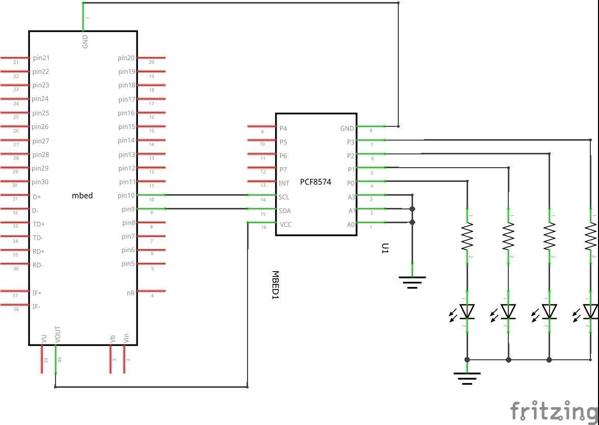
Parts List
| Label | Part Type | Properties |
|---|---|---|
| LED1 | Red (633nm) LED | package 5 mm [THT]; leg yes; color Red (633nm) |
| LED2 | Red (633nm) LED | package 5 mm [THT]; leg yes; color Red (633nm) |
| LED3 | Red (633nm) LED | package 5 mm [THT]; leg yes; color Red (633nm) |
| LED4 | Red (633nm) LED | package 5 mm [THT]; leg yes; color Red (633nm) |
| MBED1 | mbed 1768 | variant mbed; processor NXP/ARM Cortex |
| R1 | 220Ω Resistor | |
| R2 | 220Ω Resistor | |
| R3 | 220Ω Resistor | |
| R4 | 220Ω Resistor | |
| U1 | PCF8574 | package DIP16 [THT]; type PCF8574 |
Layout
This example schematic shows only 4 resistor and LED pairs, I used 8 pairs for testing
Code
This uses this Mbed library – https://os.mbed.com/users/simon/programs/PCF8574
[codesyntax lang=”cpp”]
#include "mbed.h"
#include "PCF8574.h"

PCF8574 io(p9,p10,0x40);

int main()
{
    while(1)
    {
        io.write(0x00);
        wait(0.5);
        io.write(0xFF);
        wait(0.5);
    }
 }
[/codesyntax]
Testing
You should the LED’s flashing on and off
Links
PCF8574 IO Expansion Board I/O Expander I2C-Bus Development board


